Laminar Flow Instability
As a fluid flows through a tube bundle, it falls into one of three flow regimes: laminar, transitional or turbulent. When in the turbulent regime, the flow is well-mixed and will often deliver consistent and similar thermal & hydraulic performance throughout each tube in the bundle. While this is often assumed to be the case with laminar flow as well, sometimes a natural phenomenon can occur that prevents this from happening. This phenomenon is known as Parallel Flow Path Instability (PFPI) and can cause issues with heat transfer performance when designing and operating heat exchangers with laminar tube-side flow.
Causes:
PFPI in a heat exchanger is initiated by subtle variations in heat transfer rates between adjacent tubes, leading to variations in fluid properties like bulk and wall viscosity. The overall pressure drop along the bundle can only be maintained by a change in the velocity of the fluid, which offsets the pressure in the opposing direction. This offset is what causes the unstable flow.
For any given tube in laminar flow, there exists a range of combinations of velocity and viscosity which will yield the same total pressure drop. It therefore becomes possible for multiple tubes in the same heat exchanger to experience significantly different velocities. This effect can be demonstrated graphically below, in which the solid orange line represents a range of bulk viscosities and velocities which give equal pressure drop in a particular tube.
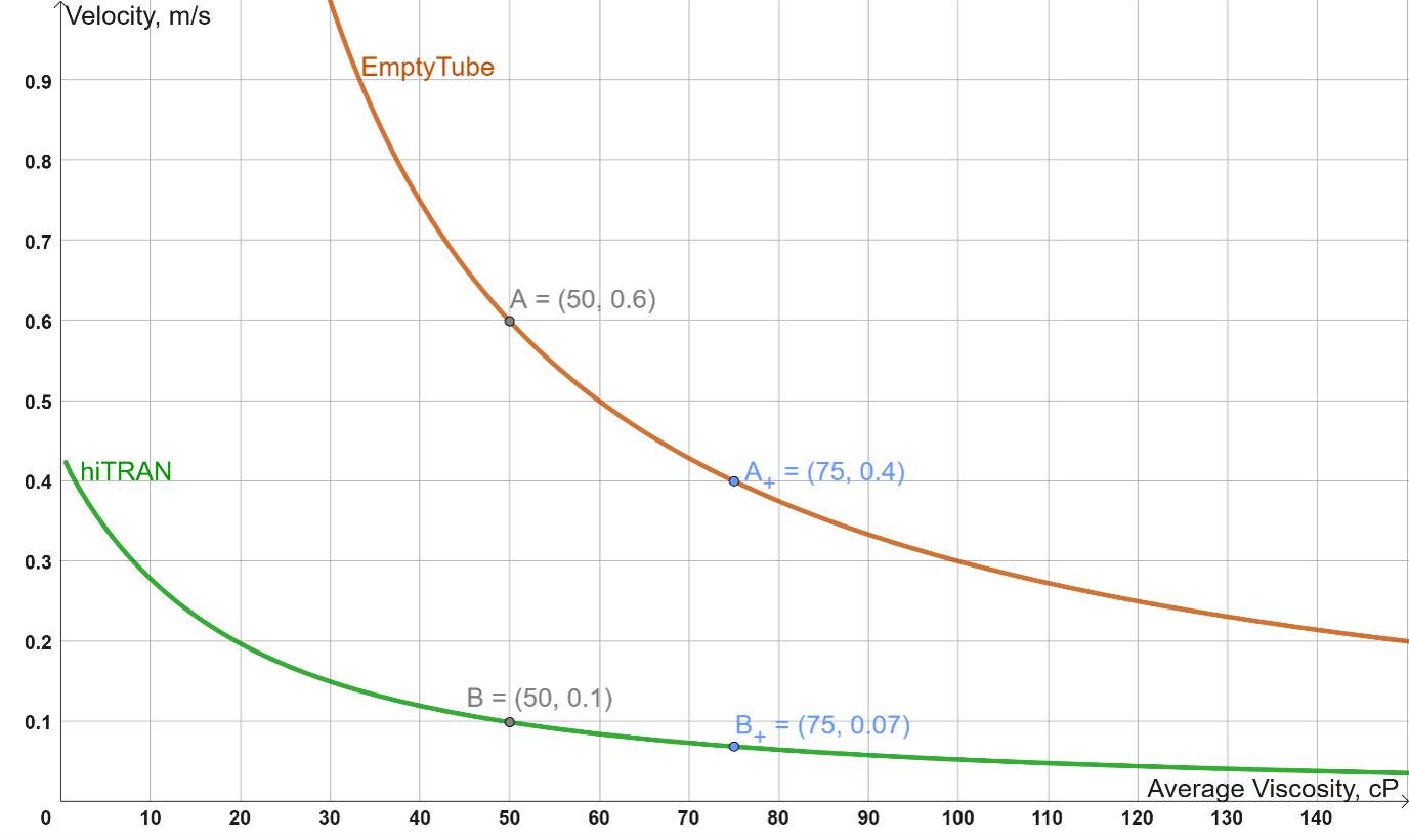
If a fluid with a bulk viscosity of 50cP enters a tube at 0.6m/s, it will correspond to Point ‘A’ on this graph. However, in an adjacent tube, if we suppose that a localised increase in cooling causes the bulk viscosity to increase to 75cP, then the velocity in that tube would have to decrease to 0.4m/s in order to maintain the same overall pressure drop across the bundle (point “A+”).
Consequences for Heat Exchanger Design:
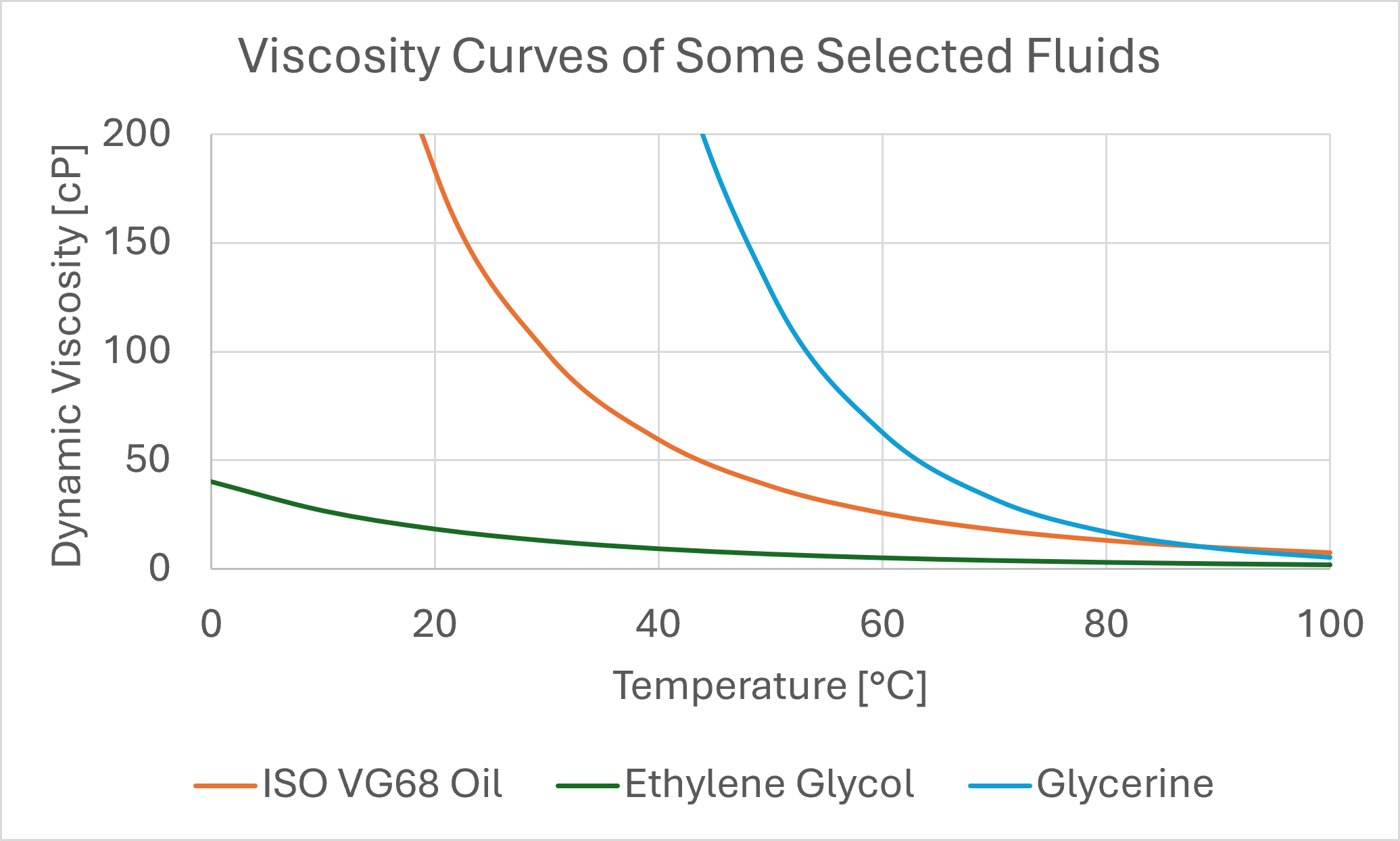
When we consider that many viscous fluids used in industry have viscosities which can vary by more than 50% over a small range of temperature, the potential risk and severity of PFPI occurring becomes clear.
Because the heat transfer coefficient is relatively constant with respect to velocity in laminar flow, PFPI can lead to large variations in heat transfer duty between different tubes. Once PFPI begins it can become self-reinforcing; a small fluctuation in the temperature of one tube will affect the viscosity, which will cause a counteracting effect on the velocity, thereby producing a different heat duty and further affecting the temperature in the tube. This cycle will continue until an equilibrium is reached between velocity, temperature, and viscosity. When integrated over the whole tube bundle, this can result in a significant shortfall in the expected total heat transfer duty.
For the design of air-cooled heat exchangers in particular, API Standard 661 (Annex C.2.6.6) expressly warns about this effect when designing with high-viscosity fluids in laminar flow. While not addressed in TEMA standards, this effect is equally possible for Shell-and-Tube and other tubular heat exchanger types as well.
Certain mitigations can be taken against this issue. In air-cooled heat exchangers, designing for a single tube row per pass can prevent variations in cooling between rows from initiating PFPI within each pass. In general, taking steps to increase the velocity to induce turbulent flow avoids this effect entirely. However, for higher viscosity fluids, achieving turbulent flow or using many passes can be impractical due to excessive pressure drop. In these cases, a different approach is required.
hiTRAN – How can it help?
The addition of hiTRAN Thermal Systems provides a simple and effective solution to PFPI; it takes laminar flow and makes it pseudo-turbulent. This offers two benefits:
First is that the pressure drop along the hiTRAN element increases more significantly with velocity than a plain tube, therefore only small variations in velocity are possible while maintaining the same pressure drop. This is also demonstrated on the above graph by the green solid line. Here, if we take the same 50cP viscosity fluid entering one tube (Point “B”) and suppose the same increase to 75cP in an adjacent tube, the velocity only reduces by 0.03m/s at Point “B+”. Consequently, any differences in velocity and duty between parallel tubes is severely reduced when hiTRAN elements are used.
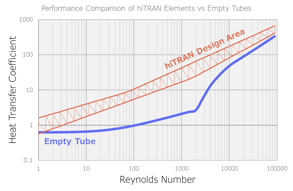
Secondly, the hiTRAN elements offer a major improvement in heat transfer coefficient over laminar flow, and the heat transfer coefficient will increase in proportion with velocity. Small variations in velocity are further offset by a stronger change in heat transfer coefficient, leading to much smaller differences in duty, temperature, and viscosity between tubes.